
ASUS ROG RTX 5090 Matrix Liquid Metal Analysis and BTF Connector Power Behavior
In-depth inspection of cooler structure, PCB layout changes, and thermal interface patterns on the RTX5090 Matrix
Hardware by Nahe Yan on Dec 01, 2025
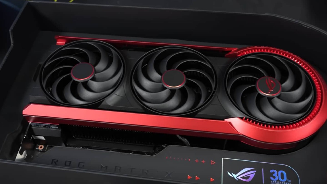
A previous investigation into the RTX 5090 Matrix by ASUS raised concerns about the liquid-metal application. Still, the time was not available then to reapply and further analyse how it was done. There was also interest in examining the BTF connector more closely.
The assumption was that the BTF connector and the 12VHPWR input might share the same power plane, allowing a mod to bridge specific pins. Hence, the card detects the BTF connector even if it is not physically in use. If successful, 800W could be pulled through the 12VHPWR connector alone. This could be useful for anyone not using a BTF motherboard or for vertical GPU placement.
Inspecting the Cooler and Liquid Metal Pattern
We began by examining the cooler, liquid metal, heat pipes, and structural layout. ASUS noted that feedback on the liquid metal application was under review for possible improvement. The PCB was further inspected after several requests for a full-size view.
When comparing Matrix and Astral designs, several changes were noted. ICs were moved, an additional mounting hole was added, circuitry was shifted, and inductors and power stages were relocated. These small but numerous changes confirmed it was not a simple Astral PCB with a connector added.
The cooling assembly includes a large nickel-plated vapour chamber with a liquid metal application pattern that appears as small dots, almost like printed droplets. A ring of thermal paste surrounds it.
The vapour chamber contacts 11 heat pipes that distribute heat through multiple fin stacks. The cooler is built into two main sections, the inner section for memory, GPU, and power stages, and a separate structure for inductors.
Microscopic Examination of the Liquid Metal
Under the microscope, the liquid metal showed a dot pattern with circular voids. At first, it appeared to contain air. Still, the disassembled state may not represent how it behaved under pressure when assembled. Larger gaps were visible, though assembly pressure may have filled them.
The top-left corner, previously noted as suspicious, was cleaned for detailed inspection. ASUS applied a protective coating over the SMD components, preventing liquid metal from making electrical contact. Cleaning showed the components remained fully protected. The alloy was confirmed to be a standard gallium-indium-tin mixture.
Reapplying Liquid Metal and Reassembling
The GPU and vapour chamber were cleaned and prepared. A minimal amount of liquid metal was applied, with a thin layer on the opposing surface as well. The GPU guard could not be installed due to the protective coating, which caused the height to be uneven.
The PCB and cooler were reassembled, including the spring mechanism in the BTF connector. After a 45-minute load test, temperatures and frequencies remained unchanged at around 3300MHz, GPU temperature near 68°C, and only a minor fan RPM difference within tolerance.
Overclocking Attempts
Overclocking settings were adjusted after being informed that the GPU Tweak range had not been extended previously. The voltage was increased to 100%, the GPU clock to +189, the memory clock to 50000, and the fan speed to around 2100 RPM.
Running 3DMark Speedway resulted in 169.1FPS, high enough to place around rank 57 in the Hall of Fame. This performance was 7% higher than the RTX Pro 6000 in the same test. With the 800W BIOS and no hardware modifications, the card approached positions typically achieved with liquid nitrogen overclocking.
Attempting to Route 800W Through 12VHPWR Only
The goal was to test if the 5090 Matrix could draw 800W entirely through the 12VHPWR connector by modifying only the BTF adapter. A riser cable setup was used to access the BTF connector.
A shorter present pin indicated which pin signals device presence. The initial theory was that bridging the present pin to ground might make the card register the connector as engaged. Ground pins were located and bridged on the adapter accordingly.
Final Thoughts
The DIY adapter worked as intended without modifying the card itself. It can be removed with no trace left behind. However, this setup runs the 12VHPWR cable far out of specification and is not suitable for daily use.
It demonstrates what is technically possible when understanding how sense pins operate and how devices interpret presence and power limits.
Also, check our other NVIDIA articles below:
- GeForce RTX 5090 Unleashed: Is NVIDIA's New Flagship the Ultimate 4K Gaming GPU?
- NVIDIA GeForce RTX 5080 Review (2025): Still A 4K Gaming Powerhouse?
- RTX 5090 Performance Testing In GTA 5 – 1080p, 1440p, and 4K Max Settings Benchmark
- RTX 5090 Laptop Vs. M4 Max MacBook Pro: Ultimate Raw Performance Vs. Battery Endurance
- NVIDIA RTX 5070 Review: Mid-Range Muscle or Marketing Hype?
- RTX 5070 Ti Review: Performance, Thermals & Power Efficiency Tested
- Asus ROG RTX 5090 Astral OC Vs. Founders Edition: The 4K Gaming Benchmark
- ASUS GeForce RTX 5090 LC Liquid Cooled GPU Review: Unmatched Silence & Speed
- MSI GeForce RTX 5090 32GB SUPRIM SOC Review: Power Efficiency, Cooling, and Gaming Performance
- INNO3D RTX 5060 Ti 16 GB X2 Review: Gaming Benchmarks, Temps, and Power Efficiency
- HP Omen 45L Review: RTX 5090 Performance, Thermals, and Value Analysis
- ASUS TUF Gaming GeForce RTX 5060 Ti Review: DLSS 4, Power Efficiency, and Gaming
- ASUS Prime RTX 5060 Ti OC 16GB Review: DLSS 4, Ray Tracing, & Thermals Tested
- NVIDIA GeForce RTX 5060 Review: Specs, Gaming, and Cost per Frame
- MSI GeForce RTX 5090 GAMING TRIO OC Review: A Monster Power GPU
Editor, NoobFeed
Gaming Hardware Updates
No Data.